Imagine a ball pen that would remember what it writes, whether sketches or hundreds of pages of text. When I thought of it in May of 2008 I did not know that such a device had already been invented, but realised that most of the elements that would comprise the invention were already there in existing technology. I subsequently learned that a very similar device to what I had in mind had been invented and was being commercialized. This was the EPOS-enabled Digital Pen and USB Flash Drive from Advanced Digital Positioning Technologies (http://www.epos-ps.com).
Unaware of the existence of a comparable device, such as the EPOS-enabled Digital Pen, I thought there must be many ways that the device I had in mind could be realized. To narrow the options, I decided to let the ball be light-permeable. The technical name of the device could be ‘an optical ball pen stylus’. The marketing people might come up with a trendier name like a Stilly: a silly stylus with memory. The descriptions below are my original ideas and are not identical to those implemented in the commercial device.
The Basic Concept
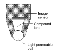
The concept relates to a handwriting or drawing implement with a ball tip (similar to those used in ballpoint pens and roller ball pens) that is light-permeable. The ball tip would be spherical and would form part of an optical lens system that would allow an image, mapped from the patch of contact of the pen stylus with a surface, to be captured on a miniature, or micro, optical image sensor within the pen stylus.
There would be multiple possible variations of the invention (and combinations of those variations) and there would be multiple applications of the different variations. Figure 1 illustrates the basic concept.
Variations of the Concept
In one variation, the optical image would be produced by ambient light that penetrates the ball. In another variation the tip would be surrounded by a light emitter or an array of light emitters, e.g. Figure 2. The light could come from a direct light-emitting device (e.g. light emitting diode, incandescent element, fluorescent element, plasma device, or laser) or could come from such a device indirectly (e.g. reflected or refracted light, light tube, fibre optic light transmission). The light could also come from the surface over which the pen stylus moves.
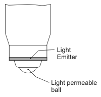 Figure 2 External light emitter
In yet another variation, light would be provided to the ball tip from within the optical pen stylus, according to the general principles of the scheme illustrated in Figure 3.
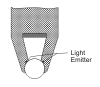 Figure 3 Internal light emitter
The ball tip could be of various sizes, depending on the area of application of the device. It is envisaged that a major application area would involve balls of the sizes currently used in ballpoint and roller ball pens. However, much smaller balls could be used, limited only by the wavelength of the light or electromagnetic radiation used. Much larger balls, virtually without limitation of size, could be used. Variations using hollow balls or cylinders (wheels or rollers) would also form part of the class of device described here. As a further variation, a fixed or non-rotating ball tip could be used.
The ball tip will generally require being very hard, although for some applications (e.g. use on a flexible screen or display) a softer, more flexible material might be appropriate. For a hard, light-permeable and tiny ball, synthetic diamond or cubic zirconia (which both happen to have very high refractive indices) could be used. Other light permeable synthetic or natural gems, ceramics, or fused or sintered materials could be used. For larger, less-hard balls a wide range of materials (e.g. glasses or plastics) could be used.
The compound lens indicated in Figure 1 could be made up of as few as one component—a light-permeable mono block, which would serve as a light transmitter, or light conductor. Its function is to convey an analysable representation of the contact area region to the image sensor. In the special case of a non-rotating tip, the ball tip and the compound lens could be one integral unit. The compound lens might also be considerably more complicated, involving materials or substances of different refractive indices and curved interfaces between components. The compound lens system could be of a fixed characteristic, or could incorporate possibilities of adjustment.
As is currently the case with optical mice (used as human interface devices for computers), the captured image would be analysed in real time to register all movements of the ball tip while it is in contact with a surface. Furthermore, the form of the contact patch would be recorded (as a movie: think of an aircraft following the meandering course of a river while recording the appearance of the river directly below), which would enable the as-drawn line to be memorized (including the line weight and texture). The resulting data would be passed on by wire (or optical fibre) or wirelessly to a computer or processor. The processor could be within the pen stylus or external to it and the data could be stored within the pen stylus or externally.
In one variation the optical pen stylus would contain ink, as in a ballpoint pen or roller ball pen. This ink would be sufficiently non-opaque that light could enter through the ball and an image of the patch of contact between the ball and a surface could be transmitted to the internal image sensor. The non-opaque ink could be of thick consistency, as in a ballpoint pen, or of a thinner consistency, as in a roller ball pen. With an internal light emitter system, as illustrated in Figure 3, there would be less of a need for the ink to be light-permeable. Various ink storage and supply systems could be used. Figure 4 illustrates a possible arrangement.
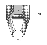 Figure 4 Ink duct around the compound lens and the internal image sensor
The general class of device might, as an alternative, contain a transparent liquid or a lubricant in place of ink. Applications of the latter could include invisible writing, depositing lines or patterns of moisture or chemicals, or applying adhesive in a manner that can be electronically recorded or viewed on a screen.
As is currently the case with optical mice, the surface over which the ball tip moves would be required to have some optically detectable variations (e.g. the texture of normal writing paper). The internal image sensor would therefore allow each continuous path of the ball over a surface to be captured faithfully.
General Usefulness and Application of the Concept
The optical ball pen stylus, as described thus far, would be capable in principle of fulfilling all the functions of an optical mouse—buttons could be added, if required, or clicking or tapping actions could be used, as with various human interface devices that are currently available. If used in conjunction with a computer display, the pointer (or drawing tip) on the display would move whenever the pen stylus was moved while in contact with a surface. The device being in the form of a stylus, the user would have more precise control over the movement of the tip than they would over the movement of a mouse. Also, if the stylus contained ink, writing could be produced on a surface, providing immediate and direct visual feedback, as well as an enduring trace of the path drawn.
However, further innovation would be required if the device were to be given the almost magical characteristic of being a pen that records whatever is written or drawn. Movements while the tip was not in contact with the surface would also require to be recorded, or at the very least the position of the pen stylus would need to be re-established each time the pen stylus was brought back into contact with a writing surface. It would be desirable to distinguish clearly between periods when the pen stylus was in contact with a surface and when it was lifted as part of a movement to the next stroke or line to be drawn. Details of an invention for this purpose are presented in the following section.
Lifted Motion Detection
The making or breaking of contact between the ball pen stylus and a surface could be detected by means of a switch, e.g. the head of the pen stylus could be spring-loaded to allow a very small displacement that would make or break a contact. Devices of this type already exist. Detection of contact-making or -breaking could also be achieved by software, owing to a change of the image of the contact patch, as registered through the light-permeable ball, by the internal image sensor.
Movement of the pen stylus while lifted from the writing surface in the course of use could be detected by means of an array of micro cameras that would surround the tip. The grip of the pen stylus could have equilateral polygonal sides so that there were only, for example, three or six different rotational positions of the pen stylus in the user’s hand. There would then be three or six micro cameras (or an integer multiple of the number of symmetrical grip positions), as illustrated in Figure 5. Irrespective of how the user might rotate the pen stylus, one or two of these micro cameras would provide images of the surface over which the pen stylus was being traversed and software analysis of the images would provide an accurate recording of the two-dimensional lifted motion of the pen stylus. Micro cameras that were not facing the surface being drawn on would not contain images of close surfaces and would automatically be de-selected for motion analysis. Another possible variation would involve a continuous ring camera (capturing an image on a cylindrical or conical or annular band of pixels of an image sensor), rather than a number of separate micro cameras.
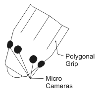 Figure 5 Micro cameras for lifted movement detection and a polygonal grip (the flat-sided grip is not necessarily to the same scale as the ball tip)
In another variation there would be only one or a few micro cameras (as a means of providing for optical analysis of the surface under the ball pen stylus during lifted motion) as in Figure 5, but the grip would be shaped to allow only one orientation of the pen stylus in the user’s hand. In that constrained orientation, the camera or cameras would face the surface being written-on or traversed during lifted motion.
It is possible that for some application areas the optical system comprising the ball tip, the compound lens and the internal image sensor might be sufficient to yield adequate data for lifted motion as well as for motion in contact with a surface. This might require a focusing mechanism within the compound lens. External micro cameras would not then be required.
There would be some remaining issues to be addressed, regarding re-establishing bearings, or relative position, where a gross movement away from the writing surface occurred or when it was required to add to previously-written work. On any page or surface two small dots or crosses could be used to define a reference frame. If the optical pen stylus contained ink, these reference marks could be made by the user. A simple protocol could therefore be devised for working with the pen stylus. This would involve placing the reference marks and touching, clicking, tapping, making gestures or hovering with the tip over one or both of the reference marks in certain circumstances to establish or re-establish bearings or, for instance, to start a new page.
Conclusion
The overall concept or invention described here is an optical ball pen stylus that could have many applications, as it would be capable of remembering what it had written or drawn. Through the use of software, diagrams that had been drawn or text that had been written by the pen stylus could be retrieved. In the case of text, handwriting recognition software could yield text documents to be edited further in a word processor. While miniaturization of all the component elements would be a technical challenge, all of the principles involved have already been demonstrated, though not in combination in a way that would constitute the present invention. One manifestation of an eventual product would be a ball pen stylus that would write on paper like a conventional pen and would be capable of recording everything that was written or drawn, without requiring special paper or any other component. The drawings or text could be transferred wirelessly to a computer, mobile phone, smart phone, printer or display screen. I want one of these silly pens that would remember. I just hope it will be very cheap, because I know I’m going to lose it!
Postscript, in View of an Existing Commercial Product
Much of the above was written before I knew of the existence of a similar commercial product. In the descriptions there are some ideas and concepts that are not part of the EPOS-enabled pen from Advanced Digital Positioning Technologies. Perhaps these ideas would have some value either to that company or to a competitor that would like to develop an even better product based on different principles. Manufacturers of ball pens might be interested in diversifying their product range. I could imagine a very low cost ball pen that would remember.
